Using RTXI for Dynamic Clamp
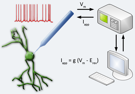
The dynamic clamp is a real-time electrophysiology technique where simulated membrane conductances are artificially injected into a cell via intracellular electrodes. It works by reading membrane potentials, amplifiing, and then feeding them into a dynamic clamp system that contains a model of the desired membrane conductance and generates a current to be injected back into the cell in real time. For digital systems, the membrane conductance is a set of equations that must be computed, whereas for an analog system, the current is the output of a dedicated electrical circuit. The injected dynamic clamp current acts on the cell in parallel with other membrane currents which, depending on the model equations, can represent ion channels, electrical coupling between cells, or synaptic input. This technique has many possible uses. With neurons, it can be used to construct hybrid networks of real and model neurons and even attach virtual dendrites. For an excellent video tutorial, see this video for the following paper in the Journal of Visualized Experiments.

Electrode Compensation and Dynamic Clamp Instability
When dynamic clamp is performed using two intracellular electrodes, one electrode records the membrane potential while the other is used for current injection. In cases where only one intracellular electrode is feasible, the same electrode is used for voltage measurement and current injection. This poses a problem for measurement accuracy because the injected current induces a voltage drop through the electrode. One method to compensate for this issue is to use your amplifier in “bridge balance” mode, which approximates the electrode as a single resistance and subtracts the voltage drop across the electrode from the total recorded voltage. This method can only be used if the electrode resistance stays constant. An alternative method is to operate your amplifier in “discontinuous current clamp” mode, in which the electrode alternates between recording the voltage and injecting current. This method is valid only if the electrode is at least two orders of magnitude faster than what you are trying to observe in the recordings.
It is important to minimize measurement errors in dynamic clamp because the artifacts propagate through the closed-loop and can lead to oscillatory instability. This instability arises when the artificial conductance is comparable to the resting input conductance of the cell and limits the conductance range that can be applied using dynamic clamp. It is directly related to the sampling delay and is exaggerated by insufficient electrode series resistance and capacitance compensation. Increasing the sampling rate of the dynamic clamp system increases dynamic clamp stability; however, this improvement, is constrained by how well the electrode series resistance and capacitance are compensated. Dynamic clamp sampling rates are usually justified by the temporal dynamics of the simulated models. For action potentials on the order of a few milliseconds wide, 10kHz is a common sampling rate. However, faster sampling rates increase the stable operating range for the dynamic clamp system and increase the maximum conductance that maintains a stable system. RTXI is capable of handling much higher sampling rates due to the low overhead in the Linux OS.
Numerical Methods
Similar to the effect of experimental measurement error, errors in simulating the virtual conductance also affect dynamic clamp performance. Methodologies for implementing the numerical integration of the gating variables typically employ first-order numerical methods, either Euler or exponential Euler. These approximations are used because of the real-time temporal constraints on how rapidly the calculations for integrating the gating variables must occur. In general, numerical accuracy increases as the time step of integration decreases. Unlike traditional model simulations, however, with real-time systems it is not practical to make the time step smaller and simply wait longer for the simulation result. For small time steps, both integration methods are comparable, but at larger time steps, the exponential Euler method performs worse than the Euler method. The error bounds for both methods can be characterized in terms of two ratios: the time step over the time constant (δt/τ), and the voltage measurement error over the slope factor of the steady-state activation curve of the voltage-dependent gating variable (εV/|d|). When δt/τ is large relative to εV/|d|, no amount of improvement in measurement error can improve the error bound due to the numerical inaccuracies caused by a relatively large time step.
For more information, see:

